Delft University of Technology
Faculty Mechanical, Maritime and Materials Engineering
Transport Technology


A.J. Schepers Offshore Tube shear. Investigation and experiment.
Experiment, Report 87.3.OS.2338, Transport Engineering and Logistics / Offshore Engineering.


1. Summary

In this report the analytical determination of the required load for cutting steel tubes and the experimental verification of this theory are discussed.

An outline of the demolition market and the way of demolishing is presented in chapter 2 of the report. Chapter 4 shows the build-up of the research project. In the theory section, presented in chapter 5 of the report, the cutting process is divided into two phases which are analyzed separately:
  • the deformation of steel tubes;
  • the shearing of steel plates. The test installation is presented in chapter 6. Chapter 7 presents the test results of the experimental verification with an existing scrap shear, cutting tubes with a diameter of approximate 600 mm.


    2. Conclusions

    2.1 Cutting force

    The deformation and shearing process together perform the cutting process. The required load for the deformation of a tube is presented in a dimensionless way ["Impacts and collisions offshore", Det Norske Veritas, Technical report 80-0036]:
    {1}:     Fdef = C * Mp * (D/t)½
    where:
                C = factor related to jaw shape of the shear and extend of deformation
      Mp = plastic moment per unity of length
        = σy * ( t2 / 4 )
      t = wall thickness
      σy = yield stress
      D = tube diameter

    The cutting load which the shear must deliver on the tube (Fcut) must be at least high enough to deform the tube, whereafter the tube can be cut. Thus,
                Fcut > Fdef

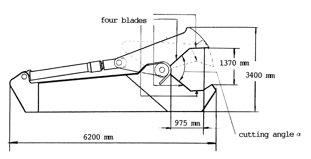
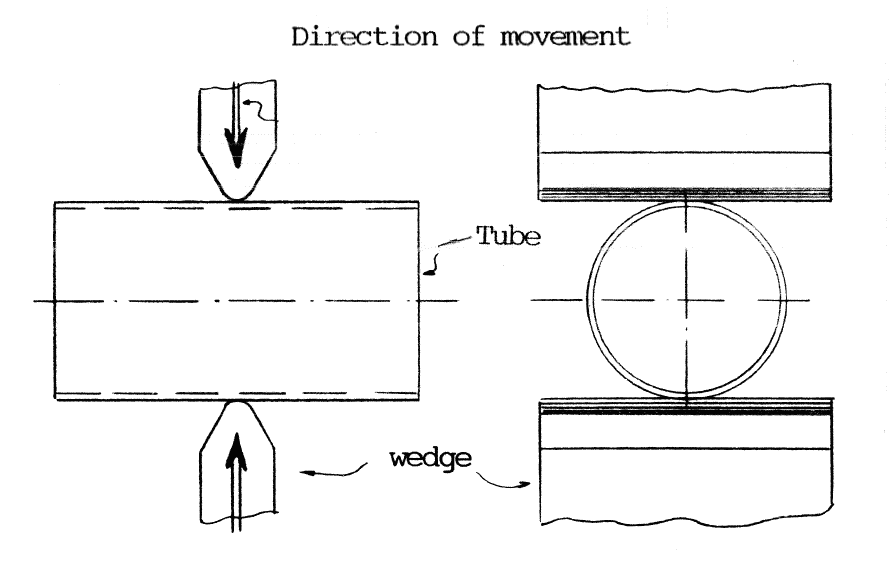
    The jaw geometry of the shear influences the required load for deformation (expressed in factor "C" in formula {1}). The test shear used at the experiments grips the tube at four locations (see figure 1). The load is divided over those four locations, concentration of the cutting load on a smaller area would reduce the required load. Watson [A.R. Watson "Large deformations of thin-walled circular tubes under transverse loading. Part II", Int.Journ.Mech.Sci., Vol.18 (1976)] has carried out tests with wedge type, diametrical gripping, indenters (see figure 2). The required deformation load at these tests is about one third of the load required at gripping the tube at four locations.


    Figure 1: Onshore scrap shear


    Figure 2: Wedge-type, diametrical gripping indenters


    The required load is reduced by optimizing the jaw configuration. Unfortunately no tests are carried out related to different jaws geometries. But from the theoretical approach is concluded that the best jaw geometry grips the tube at two diametrical locations.

    For the shearing process it is not possible to give a similar dimensionless relation. The shearing force is proportional with the cross-sectional material area between the blades of the shear, so depending on the geometry of the jaws.

    Figure 3 shows the dimensionless results of the cutting tests with the scrap shear and the values of the test with wedge type diametrical indenters.


    Figure 3: Dimensionless presentation of experimental values of tests with scrap shear and wedge-type indenters


    The maximum required force for cutting a tube is derived from figure 3 where:
    {2}:     Fmax = 55 * Mp * (D/t)½

    Thus, the design criterion for a scrap shear, related to the required force becomes:
                Fmax > 55 * Mp * (D/t)½

    The relationship between shearing force, material properties and cross-sectional area is (see paragraph 4.2 of the report):
    {3}:     Fshear = A * 0.8 * σt
    where:
                Fshear load required for shearing shear
                A = area of material between the blades of the shear
                σt = tensile strength of material to be cut

    As the shear is able to deliver a certain force (Fcut), the maximum cross-sectional area of material between the blades of the shear may not exceed a maximum value corresponding to this force. This leads to the second design criterion:
    {4}:     Acrosss-sectional < 0.8 * Fcut / ( 0.8 * σt )


    2.2 Cutting speed

    The cutting speed does not influence on the required force for the shearing process itself (proven by Craseman [H.J. Craseman "Der offene, kreuzende Scherschnitt an Blechen", Dusseldorf (1960)]). The cutting speed has big influence on the required cutting load, for deformation plus shearing. A low cutting speed allows the tube time to adjust to the decreasing space between the jaws. The deformation will go on longer and the shearing process starts at a later stage. The required load will be higher than at fast cutting. Figure 3 shows the curves of the test results for slow cutting (tube #3) and fast cutting (tube #1).

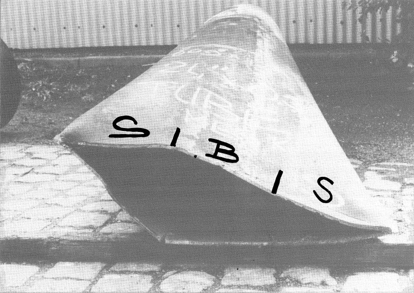
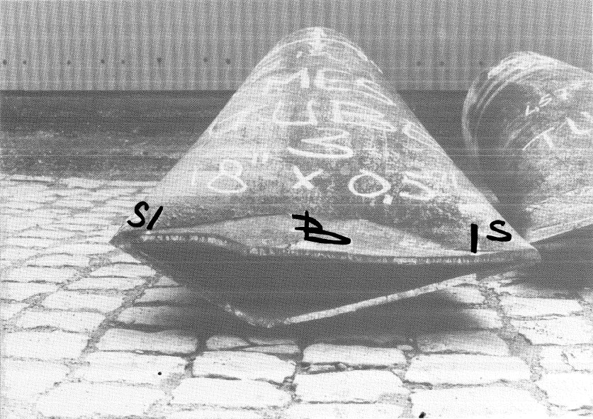
    Specimen #3, cut at low speed, did not show much signs of shearing (see photo 2) and was broken by a crack after large deformation (tube* 3 in figure 3). Tube #1 shows a much larger shearing area than tube #3 (see photo 1). The "S" written on the tube stands for "shearing area", the "B" for "breaking area".


    Photo 1: Specimen #1 after cutting


    Photo 2: Specimen #3 after cutting


    Although the required load will be lower at high cutting speed, the shear must be able to deliver the required load at low cutting speed. This is necessary for safety reasons; failure in the pump unit, failure in power supply, the shear might get stuck, could cause a lower than predicted cutting speed. So the design criterion as stated in formula {2} will not change due to a higher cutting speed.

    2.3 Sandwich tubes

    A sandwich tube construction consists of two concentrical tubes (e.g. the foundation pile in a jacket leg). At cutting the tubes, the external tube deforms until it gets stuck to the internal tube. The load on the internal tube is less concentrated as when it would be cut separately. The deformation length of the internal tube will be longer, due to the larger contact area. It is expected that this will cause an increase of required deformation load for the two tubes together related to the sum of the loads for the separate tubes. The cross-sectional area of material between the blades will be larger than as the tubes would be cut separately. As this cross-sectional area is taken into account in criterion in formula {4} for the shear design, no adaption of this criterion is required.


    3. Recommendations

    In this report an order of magnitude for the required cutting load is determined. Further investigation is recommended to the factors which effects this required load:
  • the cutting speed;
  • the presence of axial load in the tube to be cut;
  • the jaw geometry of the shear;
  • the influence of two concentric tubes. Besides the effects on the shear design itself it is recommended to investigate the way of handling the shear in an early stage. In essence there are three ways to handle the shear:
  • mounted to the hoist of a crane vessel;
  • mounted to a Remotely Operated Vehicle;
  • a combination of the above mentioned ways; thus mounted to a crane with thrusters on the shear. The disadvantage of using a crane vessel is the presence of the vessel near the jacket while the legs are being cut. For safety reasons it is preferable that the vessel would be as far as possible from the jacket. The jacket might incline or even tumble over as the supports of the jacket (the jacket legs) are being cut. The retrieval of the jacket after cutting is an other point of interest. The jacket could be installed with buoyancy tanks, picked up from the bodem of the sea after cutting or be positioned by the slings of a crane while the legs are being cut.

    Thus investigation to the operational side of using a shear during demolishing activities of offshore structure is required.


    Reports on Transport Engineering and Logistics (in Dutch)
    Modified: 2008.01.27; logistics@3mE.tudelft.nl , TU Delft / 3mE / TT / LT.