G.J. Kleisterlee
Ontwerpen van een hydraulische sproeikopaansturing.
Internship,
Report 2003.TL.6698, Transport Engineering and Logistics.
Company Vestergaard manufactures mainly de-icers and in the company's strive
for constant product improvement the actuating system of the nozzle had to be
enhanced. The nozzle, spraying a mix of water and glycol, is fixed at the
end of a boom and its motion is controlled by two hydraulic actuators.
Movement of the nozzle to left and right (horizontal plane) causes too
much wear and becomes inaccurate after intensive use. Moreover, the management
believes that integration of parts on this actuating system can reduce assembly
time and save costs when production is outsourced. Altogether reason for the
company to reconsider the current design of the system.
The main problem appeared to be the large forces on the joints of connecting
rods transmitting a translation of the hydraulic cylinder in to a rotation of
the nozzle. After intensive use these joints started to show too much margin.
A new design should improve durability, quality and functionality. In the
first stage of the project the objective was to develop a new hydraulic
actuating system to generate the movement of the nozzle. This new design had
to show less wear and slack after intensive use than appears on the current
actuating system. It had to be an overall improvement. During the project
increasing emphasis was put on the integration of as many parts possible. The
main reason for this was to simplify assembly and reduce costs. The production
of the part will be outsourced to a neighboring factory. This includes
advantages as good communication and no transportation costs. All these aspects,
in favour of integration of parts and outsourcing of production, had great
influence on the design.
First the performance of the current design had to be determined as a
starting-point for a new design. The force and speed of the hydraulic
cylinder and the reaction of the nozzle to a certain input speed at the
cylinder were established. This implies that the response of the nozzle
movement, in terms of angular velocity, to a constant speed of the piston
of the hydraulic cylinder was calculated. Some tests were run as well to
verify the forces involved and the actual force used to rotate the nozzle.
Subsequently some new concepts were considered and evaluated. Ultimately a
concept was chosen whereby two hydraulic cylinders were integrated in the
swing-axle on which the nozzle and hydraulic cylinder are presently
mounted. During the design process it became clear that the costs involved
in this concept were too high and a new solution had to be considered.
With the integration of parts as a strong condition the final design
became a hydraulic vane type rotary actuator integrated in the swing-axle
(figure I). The swing-axle is designed to cast out of stainless steel and
use CNC afterwards to finalize it. The vane motor uses two circular
pistons to rotate the nozzle. One piston is fixed to the housing and the
other one to the shaft mounted to the nozzle. By pumping hydraulic oil
in-between these two circular piston blocks they start moving away from
each other and consequently the nozzle starts turning. The volume flow and
the forces involved were optimized in comparison with the current design
by using the test results and calculations made earlier. Technical
drawings of the new design were made as well as 3 dimensional models and
sent to some manufacturers for cost evaluation. Eventually the cost was
estimated not to be higher than the costs involved with the current
design. Calculation on the weight of the integrated parts pointed out that
it will be 2 kilograms lighter than the 4,4 kg the swing-axle and hydraulic
cylinder are weighing together at the moment. When testing demonstrates that
the new design functions well, the performance has also been improved since
the rotation of the nozzle is proportional to the oil pumped in the actuator
and the speed is proportional to the oil flow (in m3/s).
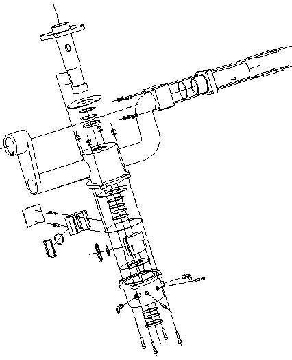
Figure I: Exploded view of the final concept for an actuating system for
rotation of the nozzle spraying a de-ice fluid.
An enlarged picture of his exploded view can be found in the
appendix of the report where a partlist is added explaining all the parts.
Reports on Transport Engineering and Logistics (in Dutch)
Modified: 2003.11.29;
logistics@3mE.tudelft.nl
, TU Delft
/ 3mE
/ TT
/ LT.